
Article by David Sutton
Being stranded in New Zealand during the lockdown (great place to be), I thought I’d have a go at building an open-ended STEAM project using Scratch. The aim is to undertake a project that includes both art and graphics, and physical computing. The idea is that these projects follow a theme rather than a detailed plan, and are likely to be developed over time by a class or community. My intention is to use aspects of the environment as themes starting with Water and Sanitation. However, as this first project is intended as a prototype, I've used Wellington Street Art as a theme (it's amazing).
Graphical Programming

The first task of taking photos and editing them to create backgrounds and sprites was great
fun. I can’t believe how many I took. Most of the editing was done using Scratch, however I also used a simple free editor.
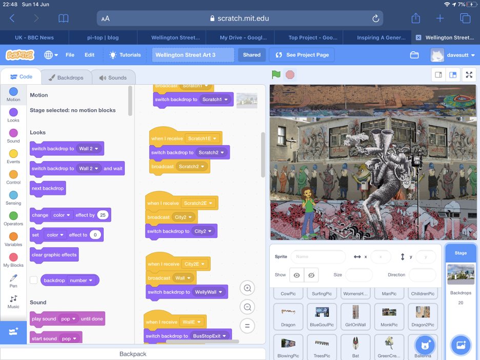
Scratch was used to develop the graphical project that displayed street art. As this was also
used to demonstrate Scratch functions, a whole range of interesting Scratch features were
incorporated. In addition to using this at a code club, it has been designed to run in the
background, on a continuous loop, for when we run open days and want to illustrate Scratch to
the wider public. The program link is included here.
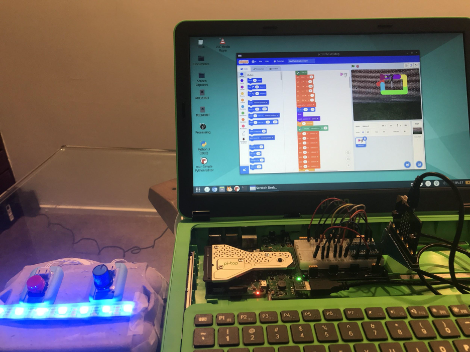
I didn't get hold of a pi-top [3] until near the end of the graphical program development so most of the work was done on my iPad. However, all the Scratch physical programming was done on the pi-top [3]. Scratch 3, is heavy on resource usage and the pi-top [3] struggled on the large program but worked fine on the smaller physical computing programs.
Two key problems had to be solved: managing the vast number of backdrops and sprites, and
enabling easy insertion of new content; adding sprites and backgrounds from other programs
developed independently.
The first problem was solved by controlling everything using the code associated with the Stage. The second by storing items in the Backpack area.
Physical Programming
The intention of this blog is to focus on the next stage, Physical Computing, using Scratch and
the Street Art theme. Two options initially sprung to mind: controlling a robot arm that would do simple painting; developing a remote paint brush that would control a Scratch paint spray. Given most of my electronics, including the MeArm robot arm are in the UK and I had an egg box and two Micro:bits to hand, I went for the second option.
Although the photo shows the remote control next to a pi-top [3], it isn’t connected and can be
used from some distance away.
Kit list
Hardware
pi-top [3]
Micro:bit - for control
Expansion board - to allow connection of the pins
Button (Lego compatible)
Rotary control (Lego compatible)
NeoPixel light strip
Egg Box - to house everything (temporary solution to be replaced by Lego)
Micro:bit - interface - receives messages from Control Micro:bit and sends them to Pi
Shield Adaptor - for connecting Micro:bit to Breadboard
pi-top [3] Breadboard - for connecting Micro:bit GPIO to Pi GPIO
Resistors 330 ohm for connecting GPIOs safely
Software
Scratch
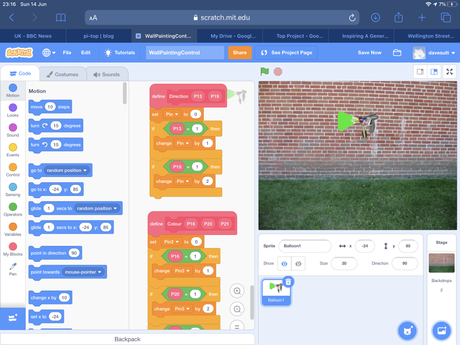
Illustration shows use of GPIO in Scratch to calculate numbers.
Micro:bit Block Language
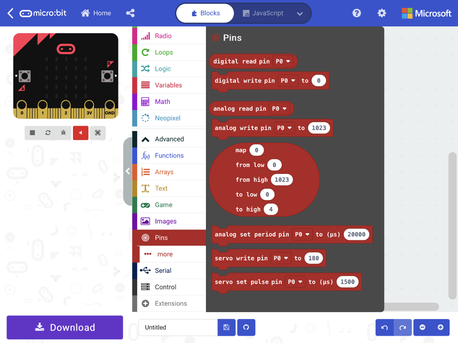
The Micro:bit language is similar to Scratch. Children who have learned one shouldn't have any problems understanding the other.
Overview of the design
The key to the design is using GPIO pins on the pi-top [3] to control Scratch. Scratch reads the
GPIO pins and treats them as binary numbers. So 8 colours can be represented by 3 pins. 000
= red, 001 = orange, 010 = yellow ….. 111 = purple. 4 directions can be represented by 2 pins.
The objective is to send the colour and direction from the control Micro:bit to the interface
Micro:bit. This is done using the Micro:bit’s simple Wireless feature. The interface Micro:bit then
sets its own Pins to represent the numbers. As these pins are connected to the pi-top [3]’s pins,
these can be read by Scratch.
Design Details
1. The Micro:bit has an accelerometer feature, such that when it is moved Front, Back, Left or Right it can be read and a number from 0 to 3 generated.
2. This number is sent from the control Micro:bit to the interface Micro:bit. The number is
prefixed with the word “direction”.
3. In order to verify everything is working OK, an arrow showing the direction is displayed
on the control Micro:bit.
4. When the Rotary Switch is turned an analogue number is read. This number is
converted to a new range between 0 and 7, representing the 8 colours.
5. The neoPixels are changed to the colour represented by the number 0 to 7.
6. Once the colour is the one desired, the button is pressed and the number sent to the
interface Micro:bit. The number is prefixed with the word “colour”.
7. The number is displayed on the control Micro:bit for verification.
8. Numbers received by the interface Micro:bit are displayed on the leds for verification.
9. The interface Micro:bit sets its pins to represent the numbers received. 2 pins to
represent direction. 3 pins to represent colour.
10. As the Micro:bit pins are connected to the pi-top [3] GPIO pins, the pi-top [3] pins will match the Micro:bit pins.
11. Scratch reads the GPIO pins and converts them back into numbers that represent
direction or colour.
12. Scratch then moves the Spray Gun in the correct direction and sets the colour of the
sprite and pen. This project sends messages from a Micro:bit to Scratch using GPIO pins. To control a robot connected to a Micro:bit, the reverse actions would be required. Scratch would send messages to the Micro:bit which would control motors or servos using a motor controller.
The question for me is “How will I link Scratch to the physical work for any future projects?” I
have now tested out a number of options including:
1. Scratch link, to connect to both a Micro:bit and Lego EV3. This is limited as you can’t add your own code to the devices.
2. Python code reading GPIO and communicating with devices using bluetooth or simple sockets (wi-fi).
3. I have an adapter for the Lego EV3 brick connector cables that lets you connect it to an Arduino. There is an extension to the EV3 language that lets you read from the
connector. So a cheap Arduino sitting on the EV3 brick communicating with Scratch over bluetooth isn’t too difficult.
4. Also lots of possibilities using wired connections and Pi extension boards.
5. Worth noting that you don't actually need to connect things together to get them to work together. For example having the Pi turn a motor that turns a Micro:bit, moves a magnet towards it or obscures the light can be used to control the Micro:bit. Lego can be controlled by using a motor to press a button on the Lego infrared control. Great for demonstrating scientific principles or just good fun.
The answer, for me, is most likely a combination of the above. It's always a balance between the kit available and what you would like to do.
David Sutton is a retired IT director and supports a local Code Code Club in the North West of England. David also gives talks and demonstrations on IT and future technologies.
He's currently in Wellington, New Zealand following the COVID-19 lockdown, with 6 weeks to go.