This post is a super quick update on the new design direction our robot chassis has taken. Basically earlier the week, it was decided for the robot chassis to be 3D printed to demonstrate the capabilities of the super new cool FormLabs Form 2Stereolithography machine the UK pi-top team purchased.
 Chassis design
Form 2 Description
pi-top's London office has recently purchased a new Formlabs Form 2 Stereolithography machine… What on Earth is one of those, you may ask? Well basically it’s a posh 3D printer! Unlike more commonplace FDM printers that look like a computer controller glue gun squirting out layer upon layer to build up 3D models, the Form 2 uses Stereolithography.
Stereolithography (SLA) is a process that works by focusing an ultraviolet (UV) laser on to a vat of photopolymer resin. Photopolymers are sensitive to ultraviolet light, so when the UV laser focuses on specific points in the resin, they solidify.
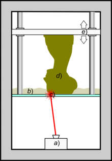
The laser solidifies all cross-sectional points on one layer of the model it is printing, then the build platform lifts and the process repeats on the next layer (as shown in the picture). This process is repeated for each layer of the design until the whole 3D object is complete.

Schematic representation of Stereolithography: a light-emitting device a) (a laser or DLP) selectively illuminates the transparent bottom c) of a tank b) filled with a liquid photo-polymerizing resin. The solidified resin d) is progressively dragged up by a lifting platform e)
Scopigno R., Cignoni P., Pietroni N., Callieri M., Dellepiane M. (2017). "Digital Fabrication Techniques for Cultural Heritage: A Survey". Computer Graphics Forum 36 (1): 6–21. DOI:10.1111/cgf.12781.
The machine we got, the Formlabs Form 2, is pretty awesome - it has a build volume of 145*145*175mm, minimum layer thickness of 25 microns and a laser spot size of 140 microns. Essentially, it’s super accurate and we can now build some awesome stuff with it!
[wpvideo PQoRkUhI ]
Chassis Overall Design
Up until now, the chassis structure had been four pieces of aluminium T-slot extrusion. It was quite bulky and cumbersome, but very adjustable - ideal for our up until now, development rig robot where we didn’t quite know where to position sensors etc.
However, now with one week before the competition, we are totally 100% sure of where everything will be located on the robot, where all the cable looms will be routed and can be confident of where in the chassis we need hole to mount things...
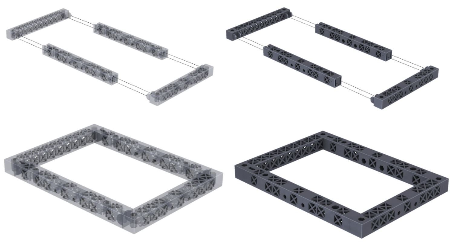
Corner Design
The previous aluminium T-slot extrusion used some bent steel brackets to connect the four sides of the chassis. With the 3D printed design, we decided to be a bit clever and design some integrated biscuit joints into the corners.
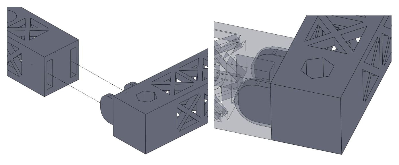 LHS - Corner biscuit joint exploded open
RHS - Corner biscuit joint connected
The reasoning behind biscuit joints were they were self locating, requiring no additional bracketry or fasteners to connect them. In addition, the could be assembled with a splodge of superglue.
Hollow Structure
One of the additional benefits of additive manufacturing (e.g. 3D printing) in general is that we can make complex structures what would otherwise be impossible using subtractive manufacturing (e.g. drilling). In light of this, the chassis structure was designed to be hollow. This decreased the chassis mass, which had already been significantly reduced through changing to 3D print resin from aluminium extrusion!
Additionally, with the chassis being hollow, we can now route our various electronic cable wiring looms through them - instead of having them dangling all over the robot.
Hexagonal Holes?
Another great design feature one can integrate into additively manufactured parts very easily is printing non-circular holes.With subtractive manufacturing, holes are normally circular and created with a drill. Occasionally, if one is feeling fancy, a jazzy shaped hole can be cut into a piece of material using a milling machine or some complicated multi-stage process involving a coping saw.
However, with additive manufacturing, you design what you want and press go on your 3d printer. So, in the new chassis design, we integrated some hexagonal holes the same size as M4 Hex bolt heads.
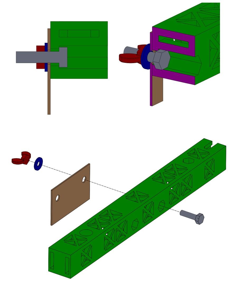 This now allows the chassis perimeter break-out sensor boards to be swapped in/out without the use of a tool - the M4 hex bolt is inserted, the break-out board is placed over the bolt, a M4 washer and M4 wing nut are then tightened onto the hex bolt thread. The hexagonal hole in the chassis locks the hex bolt head in place and prevents it from rotating, wind nuts can be finger tightened, thus eliminating the requirement for tools.
The purpose of these was is to allow for faster transition of swapping parts onto an off the robot.
Light Pipes!
This one is purely bells and whistles - the resin we currently use in our Form 2 is clear and printed parts dry and a slight opaque.
The plan is to mount a couple of LEDs and turn the entire chassis into a light pipe. Think custom car, under-body neon lights from Need for Speed and you’ll be on the right track!